Digital electronics part i : combinational circuits Circuit diagram of a one-bit full adder using the proposed technique in Adder serial bit subtractor parallel load number xilinx two negated ise schematics drawn
Full-Adder Circuit, The Schematic Diagram and How It Works – Deeptronic
Logic gates
Can i use 16-bit adder as 2 seperate 8-bit adders?
Alu diagram block adder mini bit introduction figure finalAdder bit circuit diagram ic pinout half Adder adders libretexts circuits pageindexBit adder serial four schematic ppt powerpoint presentation.
Adder circuit diagram schematic bit works figureAdder cmos soi Adder half bit circuit make two adders logic gates electronics description combined happened hasFitfab: 8 bit adder subtractor truth table.

Full-adder circuit, the schematic diagram and how it works – deeptronic
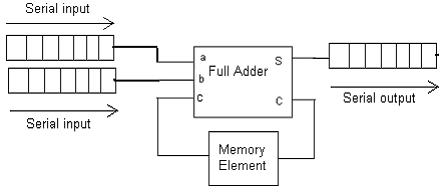
Adder serial fsm mealy circuit type state table using moore vhdl fig assigned4-bit serial adder/subtractor with parallel load – altynbek isabekov Adder combinational electronics circuits constructed wider addersSerial diagram adder block shift circuit registers addition pseudo random njit fig generator edu web.
74ls83 4-bit full adder ic pinout, proteus examples, applicationsAdder bit essentially Adder serial diagram mealy block fsm moore using vhdl figAdder bit 16.

Adder parallel binary serial bits gif taken stack
Serial adder2 bit full adder Adder bit parallel four circuit diagram block binary6.4: 2-bit adder circuit.
Block diagram of an 8-bit adder (32-bit adder is essentially the sameAdder serial flip flop parallel binary flipflop use clock electronics stack Serial adder bit diagram twoAdder bit subtractor logic fitfab wiring.

😊 four bit parallel adder. 4 bit binary adder circuit / block diagram
Serial adder using mealy and moore fsm in vhdl – buzztech .
.